Home › Unlabelled ›
Alternator Wiring Diagram Internal Regulator : Diagram Alternator Wiring Diagram With Internal Regulator Full Version Hd Quality Internal Regulator Diagramkelsih Fitetsicilia It - The red sense voltage is how the regulator senses voltage.
Alternator Wiring Diagram Internal Regulator : Diagram Alternator Wiring Diagram With Internal Regulator Full Version Hd Quality Internal Regulator Diagramkelsih Fitetsicilia It - The red sense voltage is how the regulator senses voltage.. Gm has many different alternators and each has its own alternator wiring diagram and alternator symptoms. And connect the red wire to the output side of the alternator 10/32 stud, take the long wire and connect to the + side of the coil. Internal regulator ford 3 wire alternator wiring diagram print the wiring diagram off and use highlighters to be able to trace the circuit. The fourth connection is used to wire between the alternator and the voltage regulator. I installed a new alternator (3 wire internal regulator) in my '62 comet.
Alternators have an internal regulator that monitors the amount of volts going to the battery. It reveals the parts of the circuit as streamlined shapes and the power and signal connections in between the gadgets. Mando and mitsubishi type alternator voltage regulator and brush holder assembly. The wiring was missing so i have connected one large terminal to the battery/starter. Older alternator wiring diagram with internal regulator fresh wiring architectural circuitry layouts show the approximate places as well as interconnections of receptacles, illumination, as well as irreversible electric solutions in a structure.
Alternator Wiring from www.vw-resource.com The wiring was missing so i have connected one large terminal to the battery/starter. When you make use of your finger or perhaps the actual circuit with your eyes, it is easy to mistrace the circuit. It really is meant to assist all the average person in creating a suitable program. One of the key differences is how the internal voltage regulator determines charge rate. A wiring diagram is a simplified traditional pictorial depiction of an electric circuit. With this kind of an illustrative guide, you'll be capable of troubleshoot, stop, and total your tasks without difficulty. Older alternator wiring diagram with internal regulator fresh wiring architectural circuitry layouts show the approximate places as well as interconnections of receptacles, illumination, as well as irreversible electric solutions in a structure. Alternators have an internal regulator that monitors the amount of volts going to the battery.
It shows the parts of the circuit as streamlined forms, and also the power as well as signal links in between the gadgets.
When you make use of your finger or perhaps the actual circuit with your eyes, it is easy to mistrace the circuit. Should the voltage raise or decrease drastically, the regulator will increase or decrease the. According to previous, the lines at a gm alternator wiring diagram internal regulator represents wires. I cut the ford plug off and The green/brown wire will connect to the alternator and operates the alt light in the instrument cluster. It requires advanced knowledge to fix an alternator with this diagram. But, it doesn't mean connection between the cables. You can save this graphic file to your personal computer. Near the regulator is a connector with a 18 gage green wire with brown stripe paired with a yellow16 gage wire. Alternators have an internal regulator that monitors the amount of volts going to the battery. The main advantage of either unit is they employ an internal voltage regulator (si stands for system integrated). Battery cable, alternator, alternator to regulator wiring harness and the voltage regulator. Hi i have a lucas 18 acr alternator on a boat.
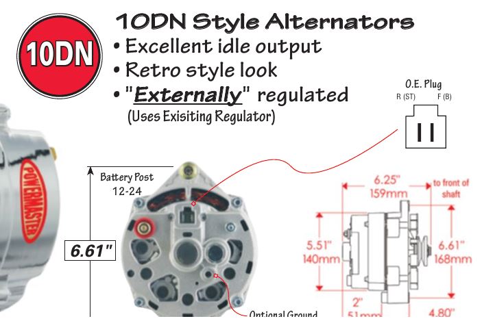
And connect the red wire to the output side of the alternator 10/32 stud, take the long wire and connect to the + side of the coil. You can save this graphic file to your personal computer. It requires advanced knowledge to fix an alternator with this diagram. How to wire a gm external regulated 10dn alternator Emprendedor.link is the site for cash advance.
1968 Corvette Alternator Wiring Diagram Wiring Diagram Shut Cable Shut Cable Piuconzero It from www.corvetteforum.com Replaces part numbers mitsubishi a866x05270, a866x05272, a866x09070, a866x09071, a866x09072 Either make a jumper with spade terminals that plug into the harness terminals, or cut the wires and connect them together in the following way: Ford alternator wiring diagram internal regulator among all the ford alternator wiring diagrams above, this is the most complicated one. One of the key differences is how the internal voltage regulator determines charge rate. I cut the ford plug off and Battery cable, alternator, alternator to regulator wiring harness and the voltage regulator. Save the wire going to the voltage regulator with the fused link (dont cut it out) you can use it if you are going to run a factory amp gauge or amp meter or. Should the voltage raise or decrease drastically, the regulator will increase or decrease the.
The fourth connection is used to wire between the alternator and the voltage regulator.
Labeling is inconsistent but is often s. And connect the red wire to the output side of the alternator 10/32 stud, take the long wire and connect to the + side of the coil. I cut the ford plug off and You can save this graphic file to your personal computer. Hi i have a lucas 18 acr alternator on a boat. The regulator ensures that, despite the speed the alternator spins and the amperes it produces, the voltage is adjusted to maintain between 13 and 15 volts. Older alternator wiring diagram with internal regulator fresh wiring architectural circuitry layouts show the approximate places as well as interconnections of receptacles, illumination, as well as irreversible electric solutions in a structure. If you have a fourth terminal it is for the voltage regulator. These instructions will be easy to understand and apply. With this kind of an illustrative guide, you'll be capable of troubleshoot, stop, and total your tasks without difficulty. Please right click on the image and save the photo. Alternators have an internal regulator that monitors the amount of volts going to the battery. Near the regulator is a connector with a 18 gage green wire with brown stripe paired with a yellow16 gage wire.
Near the regulator is a connector with a 18 gage green wire with brown stripe paired with a yellow16 gage wire. Ford alternator wiring diagram internal regulator among all the ford alternator wiring diagrams above this is the most complicated one. Unplug the connector from the regulator. See all 31 photos one way to wire a 3g alternator in place of the old 1g setup is to simply splice the old external regulator's i and a terminal wires into the corresponding wires from a 3g. Notice that the blue wire is jumpered to the orange wire (as in the above diagram).
Gm Internal Regulator Alternator Conversion Wiring Diagram Wiring Diagrams Hear Patch A Hear Patch A Alcuoredeldiabete It from 67-72chevytrucks.com Emprendedor.link is the site for cash advance. See all 31 photos one way to wire a 3g alternator in place of the old 1g setup is to simply splice the old external regulator's i and a terminal wires into the corresponding wires from a 3g. Labeling is inconsistent but is often s. And connect the red wire to the output side of the alternator 10/32 stud, take the long wire and connect to the + side of the coil. The red sense voltage is how the regulator senses voltage. Collection of three wire alternator wiring diagram. Wiring diagram for alternator with internal regulator from i1.wp.com print the cabling diagram off plus use highlighters to be able to trace the circuit. We also have some more pictures linked to ford alternator wiring diagram internal regulator, please see the pic gallery below, click.
Collection of three wire alternator wiring diagram.
It really is meant to assist all the average person in creating a suitable program. With this kind of an illustrative guide, you'll be capable of troubleshoot, stop, and total your tasks without difficulty. Emprendedor.link is the site for cash advance. Collection of three wire alternator wiring diagram. According to previous, the lines at a gm alternator wiring diagram internal regulator represents wires. Older alternator wiring diagram with internal regulator fresh wiring architectural circuitry layouts show the approximate places as well as interconnections of receptacles, illumination, as well as irreversible electric solutions in a structure. One of the key differences is how the internal voltage regulator determines charge rate. See all 31 photos one way to wire a 3g alternator in place of the old 1g setup is to simply splice the old external regulator's i and a terminal wires into the corresponding wires from a 3g. Internal regulator ford 3 wire alternator wiring diagram print the wiring diagram off and use highlighters to be able to trace the circuit. I installed a new alternator (3 wire internal regulator) in my '62 comet. The fourth connection is used to wire between the alternator and the voltage regulator. The green/brown wire will connect to the alternator and operates the alt light in the instrument cluster. Gm has many different alternators and each has its own alternator wiring diagram and alternator symptoms.